Construction
The construction process has been the bulk of the time sinks. The principal engineers have taken full advantage of machine shop open hours. The two Control-Arm, Uppers have been completed and the Shaft-Drive have all been completed. The driveshaft required a restart for this part as dimensions were not met and surface finish was not going to allow for the U-Joints to mount to the drive shaft.
The 3D printable parts were all printed in the MEC or in Hogue Hall if ABS was needed as in the case of the upper and lower motor mounts. All the parts were made to 100% infill and utilized support material. The holes drilled in the 3D printer were dilled out on the drill press using a standard drill bit or reamer depending on the application. The reamer was used in high precession location like the steering knuckles and reduction gearbox.
All the shafts were machined using the engine lathes in the Hogue machine shop, great care was taken to ensure the parts met intended requirements. Dial gages were used in the chucking process to ensure the work material kept concentric. The electric measurement read out was utilized heavily in these processes to ensure all dimensions were copacetic.

Figure 1 Driveshaft creation
The process seen in this picture is to show how the concentricity of the part was being maintained.
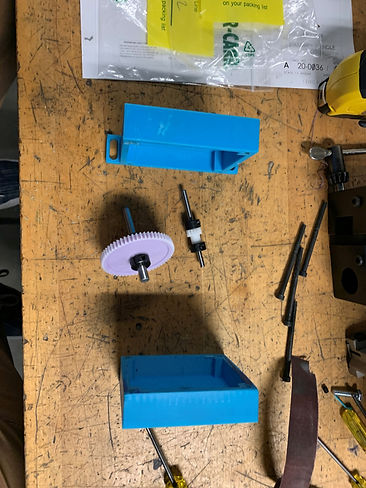
Figure 3 Gear box assembly
This image shows how the reduction gearbox is assembled and the components that make up the assembly.

Figure 5 Front suspension assembly
This is the first time the front suspension assembly has been fully assembled and tested for fit and function.
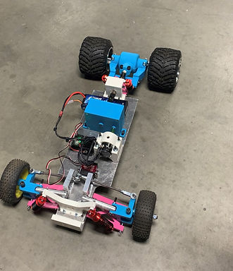
Figure 6 final device assembly
This is the completed final assembly

Figure 2 facing operation
In this image the driveshaft is being turned to the final length by facing the end to satisfy the length requirement

Figure 4 Initial Mockup
At this point the construction phases the team had decided it had produced enough machinated parts to begin the assembly process and check to see how well other parts would fit within assembly and if revisions were needed.
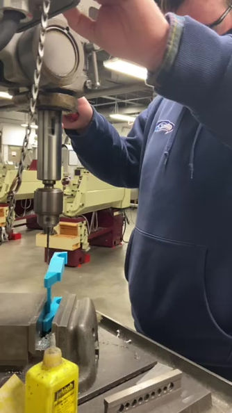
In the above video the rear axle carrier is having the support material remove from the mounting holes. The drilling was done very slow for a reason, on the first attempt with a since scrapped version of this part the part cannot be held very tight in the vice due to shape in an effort to keep it from moving very light pressure is being applied.

Figure 7 drawing tree
The drawing tree shows the order in which the device was assembled, as well as the part number associated with the assemblies..