Analysis
The analysis done in the completion of this project serves to guide the design to achieve the requirements set in the project proposal. The analysis done will provide valises for gear train ratios, steering and tie rod ends. The requirements go beyond the scope of the RC Baja competition as the goal of the car is to exceed the expected requirements of the Baja course.
Analysis has been done to ensure the following requirements are met by the design:
Drivetrain and steering
-
Must reach speeds of up to 25mph.
-
Must be able to climb inclines of up to 30 degrees.
-
Total drivetrain weight must not exceed 4 lbs.
-
Must be driven by one electric motor that confirms to current-vintage ROAR bushed or brushless motors.
-
Must use a 7.2v 6 cell battery for power.
-
Rear drive assembly must be able to be swapped in under 10 minutes.
-
Must be operated up to 50ft from driver.
-
Cost must not exceed $500.
-
Withstand minor impacts of under 20 lb-f to the side of the front tires, without catastrophic deformation.
Additionally, the following requirements were kept in mind suspension and chassis
Team member requirements – Jack Huff
-
RC Baja car must be able to be operated at a minimum of 50 ft.
-
The RC Baja car must not exceed 10 lbs.
-
RC Baja chassis must be able to withstand a 1.5 ft drop test if landed upright.
-
Chassis must be able to withstand 150N force applied to the front end.
ANALYSIS 1
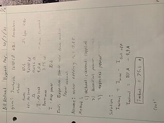
The purpose of analysis 1 is power that can expected from the motor under ideal operating conditions with power supplied from a 2S lipo battery
Figure 1 : Analysis 1 expected power

Figure 2 : Analysis 1 expected power cont'
ANALYSIS 2

The purpose of analysis 2 is find the maximum rpm and torque of the motor for later calculations in such areas as gear train
Figure 3 : Analysis 2 Max power and RPM
ANALYSIS 3
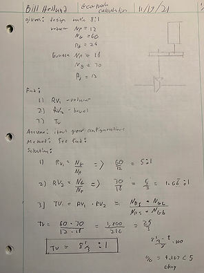
This portion of the analysis covers the gear train values for the rear gearing, transmission gearing. The requirement was to achieve an 8:1 train value per manufacturing of the motor recommendations. Mechanical design was applied to find the three needed ratios. The rear bevel ratio was found to be, 1.66:1 paired with a 5:1 ratio for the reduction gearbox. The overall train value was found to 8.33:1. The resulting documentation is: 20-002, 20-004, 20,007, 20-008, 55-002, 55-003, 55-005, and 55-006.
Figure 4 : Analysis 3 gear train
Analysis 4

Analysis 4
Using the found final gear values analysis was conducted to find the driveshaft diameter with a material of 6061 T6 Aluminum at yield stress and a safety factor of 4. The requirement was to deliver power to achieve the top speed and incline design requirements. This resulted in analysis to solve for the diameter foe the drive shaft, and will result in a final driveshaft drawing.
Figure 5 analysis 4 – Driveshaft diameter calculations
Analysis 5

Analysis 5
With the gear train calculations complete the top speed was re calculated using the final drive and rear tire size of 4 in, the new top speed was found to be 45 mph. The requirement was to reach a speed of 25mph, the analysis proved this will not be an issue. This will be used in the design of the driveshaft as a parameter to design the minimum thickness of the driveshaft keeping in mind the safety factor of the driveshafts.
Figure 6 top speed calculations
Analysis 6

Analysis 6
This analysis focuses on the deflection of the rear axle to aid in the design of suitable rear axle for the RC Baja car. The requirement was to survive the torque being supplied from the drive train. The is being conducted to confirm the material and thickness of the rear axle the analysis covers the deflection of the rear axle and produced the drawings for the rear axle and assemblies. (Drawings yet to come)
Figure 7 analysis 6 Driveshaft deflection calculations

Figure 8 analysis 6 Driveshaft deflection calculations cont'
Analysis 7

Analysis 7
This is the analysis for the tie rods. The requirement is to provide steering and directional control to the steering to the RC car, the analysis was done to first find the length of the tie rods; that length was used in a column bucking equation to find the critical stress that would cause the tie rod to fail. This analysis was all done assuming a 3/32 tie rod after design and common parts sizes a diameter of ¼ was chosen this is not a major concern as the new design is stronger than initially calculated. This resulted in the dwg 20-005.
Figure 9 – Tie rod stress calculations

Figure 10 – Tie rod stress calculations cont'
Analysis 8

Analysis 8
This is the analysis for the Upper Control arms, the requirement is it withstand a drop of 1.5 feet. Part a of the analysis is to finds the length of the upper control arm with the current sketched design. Part of the analysis was a column buckling calculations this is thought to be the most likely failure point. The analysis found that the control arm can support 290lb with a safety factor of 3. This design was chosen as the project would already be ordering 9/16 6061 T6 round stock and this would ese production, cut down, on cost and reduce wasted material. The Upper Control Arm dawning is 20-006.
Figure 11 – Upper Control arm strength analysis
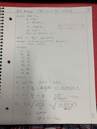
Figure 12 – Upper Control arm strength analysis cont'

Figure 13 – Upper Control arm strength analysis cont'
Analysis 9

Analysis 9
The requirement for this analysis was provide locomotion to the RC car, the focus of this analysis was to design the transmission gear reduction, earlier analysis was done to find the transmission gear reduction velocity ratio. The analysis led to the selection of a 12-tooth pinion gear and a 36-tooth driven gear with a gear pitch of 20. Analysis was done to find center distance and meshing factor mf ratio for the two gears. The ratio was found to be 1.6. This resulted in dwg; 20-007, 20-008, and part 55-002, and 55-003/
Figure 14 Gear selection and design for transmission

Figure 15 Gear selection and design for transmission
Analysis 10
Analysis 10
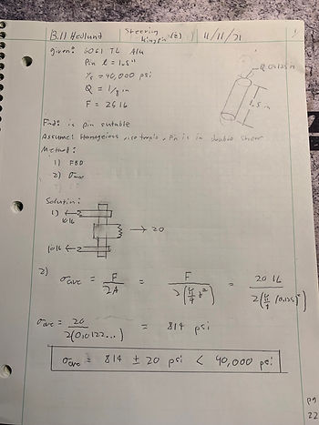
Analysis 10 was to conduct to test the strength of the steering king pins for the front steering. The requirement was to withstand 20 lb-f side impact without deformation of the steering components. The analysis was done to confirm king pin size selection was correct, the analysis was done for double shear and found that the kingpin size is suitable for the requirements. The resulting documentation is 20-010.
Figure 16 Kingpin design
Analysis 11

Analysis 11
Analysis 11 was conducted to find the cotter pin size and material. The requirement was to waistband a 20lbf in double shear. Statics analysis was preformed to find the max shear stress, materials analysis was also performed to find the material selection. The pin chosen was a 316 stainless steel pin with a diameter of 3/64. This part is intended to be purchased and resulted in dwg 55-009.
Figure 17 cotter pin selection

Figure 18 Cotter pin selection cont'
Analysis 12

Analysis 12
The twelfth analysis was preformed to produce the driveshaft. Simple geometric analysis was used to find the lengths for the driveshaft dimensions. Statics analysis was used to resolve for the shaft diameter with the corrected input torque values 6.85 ft*lb. The new diameter was selected to be 0.500in. The final length of the driveshaft was determined by using 55-004 u-joints. The resulting part drawing was 20-010 driveline shaft.
Figure 19 Driveshaft design

Figure 20 driveshaft design cont'
